Circuit Explanation / Part
Recommendations.
Note - Most parts
are equivalent to Tangents’, his explanations are excellent, check em out.
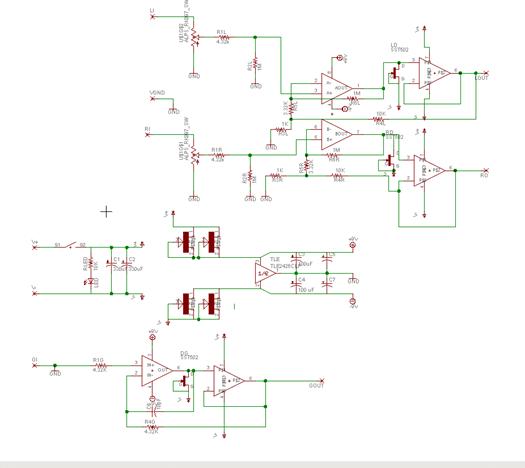
Similarities with PPA
-
Rail isolated opamp rails - JFETs beneath the
board, they isolate the opamps
3
channel differential topology -
Sinks and sources current well.
Dissimilarities
Unified opamp rails - all 3 opamps have a
single rail, instead of 3 for PPA, less current draw, more channel crosstalk.
Class-A - Not done
by cascades, but by a single CRD.
Rail caps - Less
rail capacitance .. about 1/3rd.
Less current draw
- On a low current mode, 20mA maximum, 10 hours of play time.
Part Recommendations..
JFET - the 4 JFETS
on the main rail act as current sources using JFETs,
they output constant IdSS, if you don’t know what
this means, just use the default value, SST310. If you want more / less draw,
you can get tricky and use ones with lower IdSS (or
higher, for better opamp slew).
R6 - This
determines the bandwith of the L/R channel, lessen the
resistor if your amp oscillates. Should fix it.
Buffer - Ground
channel MUST use open-loop ground, if you don’t know what that means, get a
BUF634 / LM6321, its really not worth it to get anything else, it’ll oscillate
like hell. The other 2 buffers will work with closed-loop buffers given that
your bandwith is not too mismatched..
(rule of thumb, gain stage bandwith
< buffer bandwith)
Jumper - If one
puts a jumper across the jumper pads (beneath the pot, left of the buffer) it’ll
put the BUF634 into wide-band mode. Putting a controlled resistance will put it
somewhere between quiescent mode and wide band mode, wide band sounds better,
but basically draws 4x more current..
Class-A - Pads DG
DR DL which use the SST502 for biasing..
LED - should be
high brightness, or the 10k resistor will overwhelm the LED.